ahuranga.com > 2D Illustrator
path simulation
2D Illustrator Robot
Tools used: Matlab, Python, Raspberry Pi, CATIA
Background
This project started as a product design project. We could create and design any product as long as it would improve on a design. We wanted to focus on a product that could draw on small surfaces. We originally wanted to design a robot that could write a menu on chalk. Our initial design was simply a CNC machine that held chalk and was oriented vertically.
the team took a systems engineering approach to develop the product. We set a series of requirements such as the hardware, software (input), software (processing), controls, and motors. We split the team to take on each requirement, constantly communicating any changes that might affect other requirements.

I mostly focused on the software and controls. I developed an edge detection algorithm. Although there are plenty of open source scripts that can detect edges, the issue arose while exporting the image. In order to control the motors, we needed the output to have specific properties and be a specific file type. It became easier to just develop a program from scratch. After completing this task, I was able to process the result and develop the motor controls. I used my knowledge from courses in mechatronics, control systems, mathematics, and engineering programming to meet the system requirements.
We quickly realized two things. One, this was an expensive product that does not solve any real problems. And, two it can not be scaled up. We then pivoted to a new design, instead of a quasi-CNC machine, the robot would be guided by four stepper motors at each of the four corners of the canvas. This way we could scale to any combination of drawing surfaces.
The main goal was to design a robot that could assists artists in the creation of murals. During the initial research, we determined that the first stage of drawing a mural is drawing the initial outline, this process can be difficult and time consuming. The goal was not to eliminate artists completely, but instead to save time.
After consulting with several artists, it was determined that we do not wish to eliminate them from the equation. Instead we wanted to provide a tool for them that would allow them to save time. Drawing the outline of a mural can be very time consuming, we would provide them the opportunity to finish the outline in one night. We also wanted to create a device that can be easily modified to draw on various canvases and of different sizes.
Motor Assembly
The new configuration will not limit us in terms of size, much like a track and rail design. If we were to use a rail design, we would need to build a robot for each case making it prohibitively expensive

The stepper motors are controlled by a microcontroller, will position the centerpiece housing and the spray nozzles to the exact position they need to be. It will accomplish this through path generation specified by the software.
The design of the motor control was kept simple for ease of manufacturing, assembly, and maintenance. The stepper motor will be controlled by software to rotate a certain number of ‘counts’ to position the spray nozzles into the correct location. It will achieve this by turning the wire spindle and increasing/decreasing the amount of wire between it and the spray nozzle. In order to simplify calculation, and achieve a constant radius for the wire spindle,
The four motors are connected to the centerpiece using four cables. This configuration was chosen due to it’s stability and it allows us a greater freedom in terms of motion and motion control. Suction cups can be added to the motor assembly which would then allow it to be placed on glass.
Centerpiece
The Centerpiece Housing is the primary motion and working medium delivery component of the system. Various concepts were evaluated through trade studies to ensure fulfilment of all the system level requirements.

The four arm linkage was the optimum configuration for applications on a rectangular vertical surface to maintain positional accuracy of the centrepiece housing within the allotted target area. To avoid force couplings being induced on the statically intermediate structure the load paths would be able to rotate and the angle between adjacent arms changed for each unique location.
The centerpiece was designed with a disk shape.The disk’s symmetry assists in the balancing different cable tensions. Cable linkages would utilize a swaged cable end locked into the centerpiece housing using ball lock pins for easy user setup and breakdown. The disc shape geometry also allows for scaling up or down dimension for further customization or model variations. On the back of the housing would be the entry point for paint and air supply to the nozzle routed from the lower paint reservoir. It also includes a shield at the back to better contain the paint when sprayed on the surface.
Robot Control
The main difficulty we encountered was determining how to control the robot. Due to my interest and background in math, I was tasked with developing the algorithm that would generate the robot’s path.
Initially I wanted to focus on a simple case where the robot would be used to draw a logo on a wall, for example. I saw a mural of the San Jose Sharks in downtown, and tried to use the logo as an example. Fortunately, the logo has well defined lines which made the edge detection process slightly easier.

Example project. The robot would draw the right image, the artist would then fill in the details.
For this project I focused on the following three areas:
- Path Generation
- Postprocessing
- Motor control
The first challenge was specifying the robot’s path. We needed a system that could track the robot’s current position and from there calculate a what motors needed to be on, at what speed, and for how long. The first step was to draw an outline that the motor could trace. I took what I had learned from a class on signal processing and applied it to this problem. I ended up using mathematical tool called wavelet transforms that could apply filters to an image in order to extract and manipulate the image details.
The High (H) and Low (L) filters are applied in the vertical direction, and again in the horizontal direction. In practice the HH extracts changes in the diagonal direction, HL in the x direction, LH in the y direction, and LL is what is left after extraction. I then repeat the process with the LL matrix. Adding all the matrices together, along with some manipulation and some thresholding, should result in the outlines of the original image.
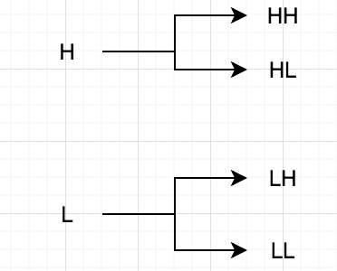


The images above represent the result of applying the H and L filters.
- The Bottom Right quadrant is the HH and it extracts changes in the diagonal direction.
- The Bottom Left is the LH which extracts vertical changes.
- The Top Right is the HL filter, extracting horizontal changes.
- Finally, the Top Left is the LL and is simply the result after the other features have been removed.
On the image on the right I demonstrate how different threshold levels affect the final result. Most free edge detection algorithms do not have this feature, only the paid versions do. One of the great properties of wavelet transforms is the concept of Multiresolution Analysis. Basically this allows me to perform the same procedure on the resultant image in the top left. This allowed me to filter the image a second time and extract some features that were missed the first time.
At this point we had simply a set of coordinates where the robot had to travel, what we did not gave is the optimal path. At this point I found an open source software that can trace a path and convert it to a vector file. The sharks logo is great for edge detection but it has many lines and would be complicated to test, so I decided to start with the logo from my alma mater, the University of Arizona. This should be easy to extract and relatively easy to draw. I generated a SVG file using inkscape. The SVG format contains the code for a path that the computer extracts and can draw at any resolution. I had to built a program that would extract the path in a way that could be useful to our project.


From left to right: Original Image, Extracted edges, partial SVG code.
At this point I should mention there are countless programs, both open source and proprietary, that do what I just did and much better. However, these are designed for use in CNC machines with a single x-motor and a single y-motor. Our design will have four motors which all control both x and y movement. All this means we cannot use that software as is.
SVG files is similar to gcode in a way, it specifies coordinates and instructions where to move. The difference is that gcode treats all curves as circles of varying radius and arc length. SVG on the other hand, all curves are Bezier code, this results in much shorter code vs gcode.
In the code in the top right picture you can see three letters “M”, “L”, and “C”. These are the instructions on how and where to move, this is our path. Occasionally you can also encounter “Z”, but this does not affect our robot. Now we have the path that the robot should follow. The next step is to modify it to a format that can control the robot. In order to do this we must first determine what the letters and numbers mean.
First, the numbers are simply coordinates with the origin being the top left corner.
“M” simply tells the machine to move to a specific point without drawing anything. This represents the end of a particular path and moves to the start of another line.
“L” tells the machine to draw a straight line between each set of points that follows the “L” until it encounters another letter.
“C” refers to a Bezier curve, this is where I ran into the most difficulty. In order to draw a curve you need a set of start and end points as well as one or more control points. Wikipedia has a much better explanation. Below are animations of quadratic and cubic curves. The “C” path consists of both cases.

There is a complexity arises due to the fact that sometimes the curve is quadratic and other times it is cubic. Basically, the beginning of the curve is always quadratic with the subsequent points being cubic, however the third point is reused as the first point in the new curve with three new control points. The final third new point is re used as the first point in the next curve, and so on. The end of the curve is usually quadratic.
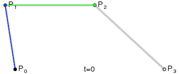
Below is my first attempt at interpreting the SVG file and converting it to something that can control the robot. While developing the program in python I wanted to see if I could test the program under different conditions to see if it really works. The first thing I did was to delete some points in the middle and added an M in order to have it move to the next point in the middle of the path. If you do this directly in SVG you can get some strange results like curves where there should be none (trust me I tried). I also had the program end in the middle of a line. Again this can produce weird results in SVG while it tries to complete a curve when it expects and end code and there is none. The results are below. Remember, the path is incomplete on for testing purposes.

The robot's path would start at the green, and draw the blue line. The orange represents where the robot would move without drawing anything. Robot would then proceed to draw the blue line, finaly ending at the red dot.
The equation for the Bezier curves are:

I had to create a set of loops that calculate the points on the curve for different points in time.
It is important to notice that the middle control points never fall on the curve, if you are not careful, instead of drawing a circle you wil draw a rectangle. The opposite is also true if you draw a curve instead of a line.
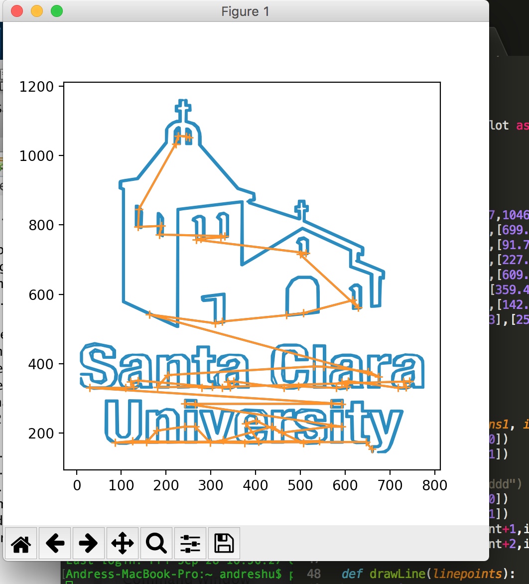
With everything seemingly working well, it was time to try out the algorithm on a more complex design, the logo from my new alma mater.


From left to right: Original image, final path.
[Update 10/13/2018] I am currently in the process of testing the robot on a small scale. I have the path and a program that controls the stepper motors using Raspberry Pi. The partial code is below. Essentially, each curve creates an independent loop where the raspberry pi calculates its position and the position where it needs to be. Using this information, it tells each motor to move a number of steps until it it at the desired position. And the loop repeats until each curve is drawn. I will post the results when complete.