ahuranga.com > Autonomous Robot
Autonomous Robot (or why you should fail fast)
This project originated in a mechatronics course I took. The basic requirement was to create an autonomous robot that could traverse a hallway, and drive around any obstacles it encountered. Once we accomplished this goal, then the requirements would be expanded to include a way to communicate the safe path to any subsequent robots robots so that they may travel that same path.
The robot would be equipped with a compass and an ultrasonic sensor. During the design period, we also considered future designs which would contain a GPS unit in order to track the robot’s location. Additionally, we considered the possibility of including an accelerometer in order to maintain an accurate location measurement. I will discuss this to a greater extent below.
The initial goal was to create an autonomous robot that could traverse a hallway, and drive around any obstacles it encountered. If we could accomplish this goal, then the requirements would be expanded to include a way to communicate the safe path to any additional robots behind it.
Two solutions were evaluated. First, the simplest solution was to use the walls as guides. The ultrasonic sensor would be used to take two measurements, the distance directly in front of the robot (“safe distance”) and the distance to the right of the wall (“wall separation”). The solution was to hold the wall separation fixed to 20 cm, if the distance ever deviated by more than 5%, the robot would turn and travel until the requirement was reached. This would allow it to easily go around corners. If the safe distance in front of the robot was greater than 30 cm it would travel 20 cm forward and repeat the process. If the safe distance was less than 30 cm it would turn left to avoid the obstacle.
Once we had a solution, I had a different idea. Instead of taking two measurements, I wanted to have to ultrasonic sensor rotate 180˚ taking measurements at fixed intervals. In essence I wanted to map out the entire area in front of the robot in order to create a 3D representation of the entire area that could be used to determine the optimal path. I ran a small scale test, below is what I wanted the output to look like:

Small scale test layout

Expected test results
Procedure
In order to create a scan of the room, I attached the ultrasonic sensor to a stepper motor. The motor would face directly to the left and rotate slowly 180˚. It takes the motor 256 full steps to rotate half a circle. Every 16 steps (every 16˚) the motor pauses and takes a measurement. In the end there are a set of 17 data points of an angles and distances. After this it is only a matter of using simple trigonometry to convert the polar coordinates to xy coordinates. The code is available here. The program writes a csv with the x and y data points where a separate program plots the results. The ultimate goal was to have the robot know it's position at all times, take several measurements, and combine all the data points to create a full scan. At first the robot would only turn parallel to the ground (about the z axis), but eventually the goal would be to rotate about the x axis as to create a half sphere of coverage.

Wiring diagram

Rotation animation
For the first small scale test, I had the ultrasonic sensor rotate 180˚, taking measurements every 16 steps. Since we know it’s position and the length, using simple trigonometry we could deternine the position of the walls and obstructions. It would then plot the points on an xy coordinate system, determine the optimal location, move to the next location, and repeat the process updating and refining the points. Unfortunately, during testing, the resulting map looked like this:

Small scale test result

expected vs. actual result
At first I thought there was an error with my math, but after triple checking everything I found the problem. Ultrasonic sensors have many advantages over light based measurement tools, first they can detect clear objects such as water and glass windows. Laser beams would simply pass through and result in inaccurate measurements. However, the ultrasonic sensor is only accurate when the surface is parallel to the sensor. Ultrasonic transmitter sends a wave signal which then bounces off the surface where it is detected by the receiver. The microcontroller measures the time between the transmission and when it is received. Knowing the speed of sound, we can then calculate the distance travelled. Unfortunately, if the surface is at an angle, the sound bounces off the wall to another wall, and finally to the receiver. This is why the results are only accurate at 0˚, 90˚, and 180˚; and inaccurate at all other angles.
During testing we calibrated the sensor pointing directly at an object and never thought to measure at an angle. I started testing the ultrasonic sensor and sound that it starts to fail at a deviation of 25˚. In order to work correctly, I will have to use a light based sensor. The one I found was the VL53L0X time of flight sensor, it is relatively inexpensive at $15, however it has a max range of 100 cm. It would be accurate in my small scale test, but would be inaccurate at a full scale test.
New Procedure
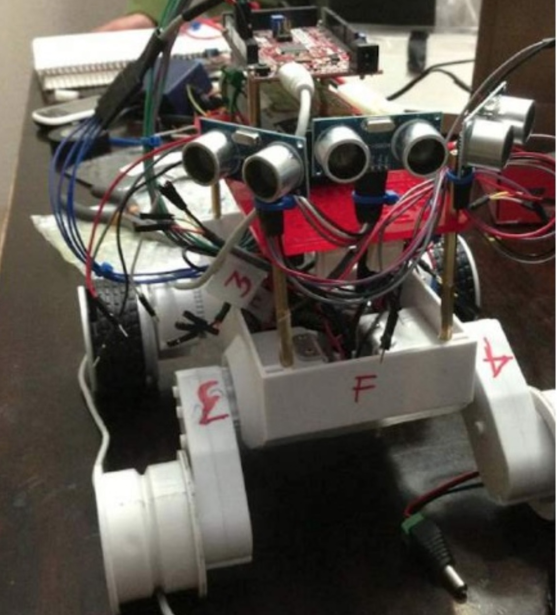
Even though the overall idea failed, there were some positives were gleaned from the test. First, the ultrasonic sensor is accurate if used at the correct angle. Second, the spinning idea worked very well meaning we could use one sensor instead of three, thus reducing the amount of things that could go wrong. In the end we modified the code to only take three measurements, directly in front and at each side. Below is the final state diagram.
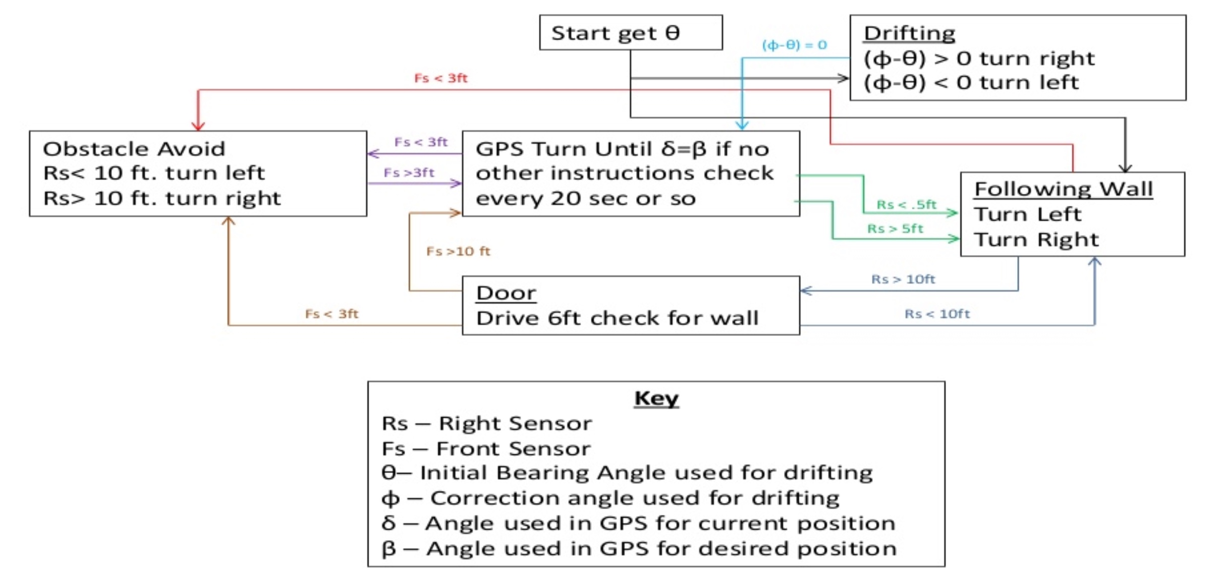
State diagram
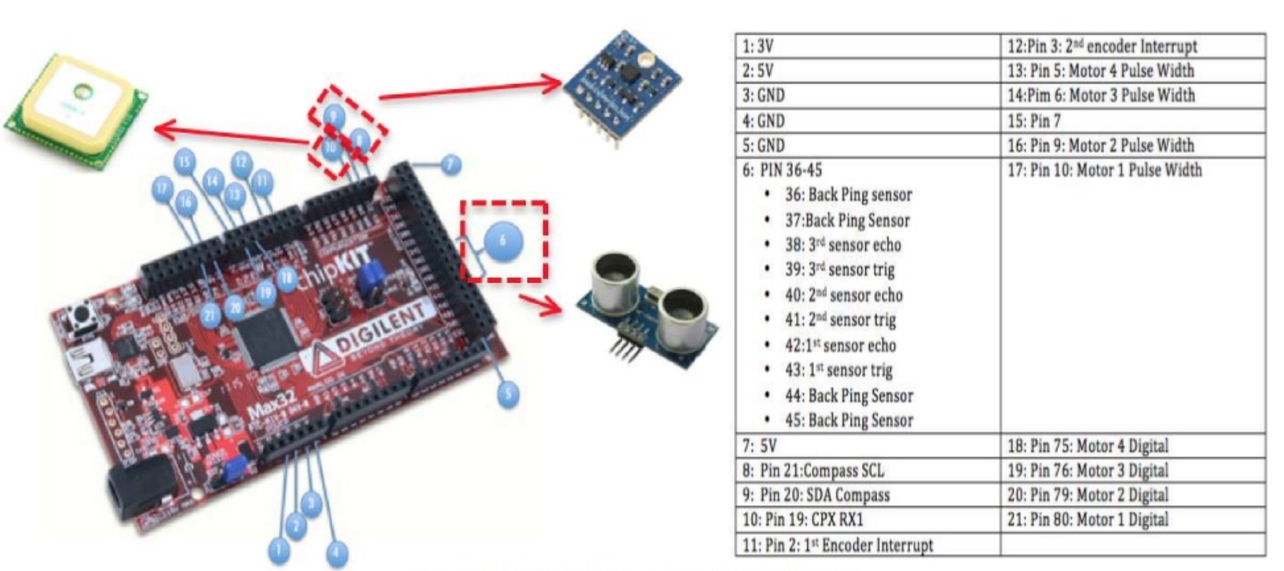
Pin Diagram
We used a compass in order to ensure the robot stays at a default heading, only deviating if there is an obstruction or a change in the guide wall. If the ultrasonic sensor detects a change, it will follow the algorithm below to avoid it and if possible, return to the default state. If the robot goes around a corner, it will not return to default but will still be able to navigate to the end. Finally, we adjusted the safe distance range for the large scale test, this resulted in a much smoother run since the robot did not have to take as many measurements.
I still wanted to prove that mapping a room was possible, I ran a final small scale test. In this test I used the compass to give the robot a constant heading and took measurements every 5 cm directly in front and to the sides only. This gave me data points in the x and y plane which I plotted below. I disabled the obstacle avoidance routine in this test.

Result

Code
There is still some variance from the correct values but the results are much better than before. The results can be improved by taking two measurements at each point and averaging the results.
Next steps.
I am on the fence on what I should do next. On one hand I want to buy several TOF sensors for a 3D scanning project I have in mind. I would place the sensors on a plate that will spin around a stationary object. Knowing the measurement angle and the distance I should be able to recreate the object as a 3D model. Unfortunately, while researching similar projects, most people have been unable to produce accurate results. The main reason is that most TOF sensors to not emit a focused beam but instead emit a beam that becomes wider over greater distances. Similar to flashlights vs lasers. If you want to ensure you detect an object you use a flashlight, if you want to detect a precise point you use a laser. There is simply too much variation in the results to create an accurate 3D map. If I were to work on this project it would be as a proof of concept more than anything.
As for this project, we ended up using the procedure I mentioned earlier of only taking two measurements at a time. It accomplished the goal but we could have done better. I want to create a fully automated robot capable of creating a 2D scan of a room. The main problem I am running into is that any distance greater than 2m produces inaccurate results, and in order to scan a full room, the robot would have to travel around the whole room taking measurements. In essence, this means that not only would I need an accurate TOF sensor, a compass, and a very accurate GPS, as I would need to know the angle (relative to TN), as well as the robot’s precise location in order to create an accurate grid.