High Pressure Combustion Chamber
The project was part of a year long collaboration with several other gradute students of different backgrounds. We developed a high pressure combustion chamber capable of studying the behavior of high hydrogen content fuel under gas turbine engine conditions. The chamber would feature a window for visual analysis. The group developed a concept for a cooling design system allowing for the operation within a given temperature range. Finally, the chamber had to be designed for transportability. This meant that it had to be easily disassembled, lightweight, and durable.
The chamber was analyzed using Finite Element Analysis (FEA) and Computational Fluid Dynamics (CFD). Final report detailed FEA/CFD results, manufacturing details, material selection, and safety considerations
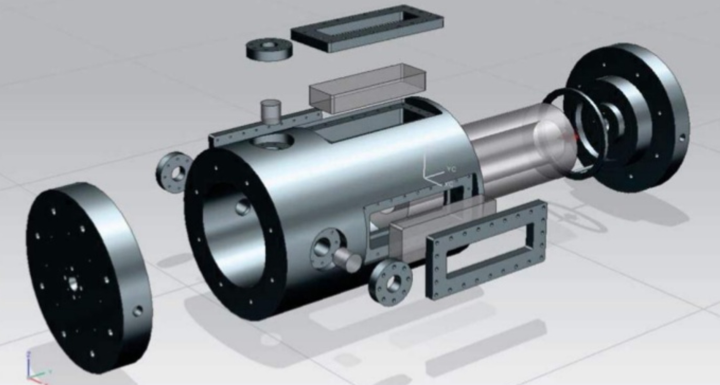
Final design

CFD results

Heat Transfer results
Hand pliers
This project was done as part of one of my mechanical design classes. The goal of the project was to design and analyze a set of pliers. Considerations were taken in terms of cost, manufacturability, human factors. The first step taken was performing hand calculations to determine stress concentrations and weak points. Loads were taken from experimental data during in-house testing. Pliers design was modeled using NX and analyzed using ANSYS and NASTRAN. FEA results showed maximum stress was well below the elastic limit. Material chosen was a grade of stainless steel . The reasoning is that we wanted to prioritize long term use and wanted a material that would not rust while still being relatively inexpensive to manufacture.

Final design
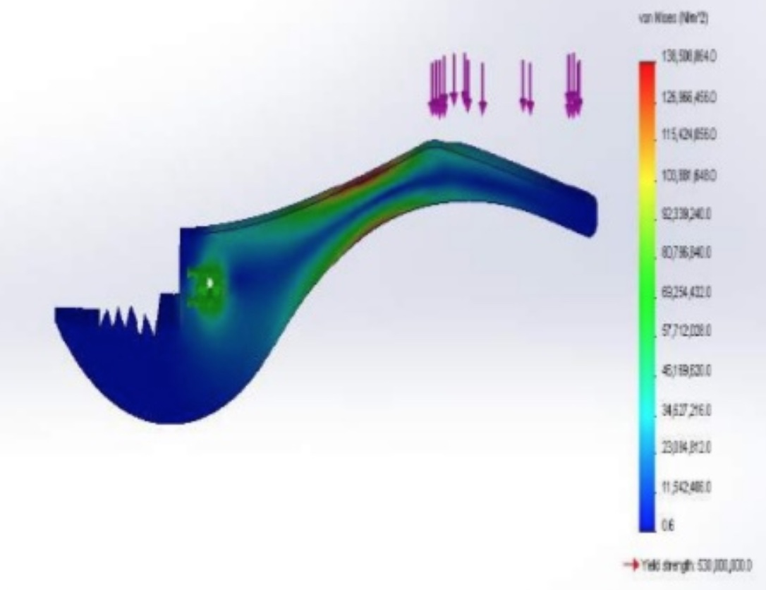
FEA results
Mechanical Vise
This project was another in the same design class. This time the goal of the project was to design and analyze a mechanical vise. Considerations were taken in terms of cost, manufacturability, human factors. The handle would be able to move in order to give additional leverage if needed. Loads were taken from experimental data during in-house testing. Pliers design was modeled using NX and analyzed using ANSYS and NASTRAN. Since the handle was allowed to slide, we had to analyze the handle for the worst case scenario where the handle was slid all the way to one side and the load being applied on the opposite side. The material chosen prioritized cost and ease of production while still having a safety factor of more than 2.0.
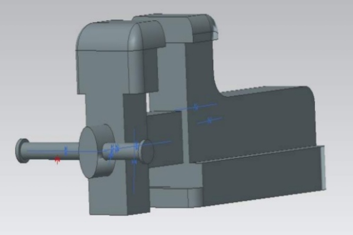
Final design

FEA results
Airfoil flap mechanism
This is the most recent mechanism I have worked on. I have always been fascinated by commercial aviation, and I have been curious as to how the flaps move. The flaps are extended during takeoff and landing as it increases the lift of the aircraft. During landing, they allow the aircraft to be flown more slowly without stalling, and they reduce landing distance.
In this model I took inspiration from the slotted flaps on a 737, while making a few changes for improved movement. Airfoil coordinates taken from airfoiltools.com. The outside of the wing is lofted to account for differences in the wing shape, which created its own set of challenges.
Animation
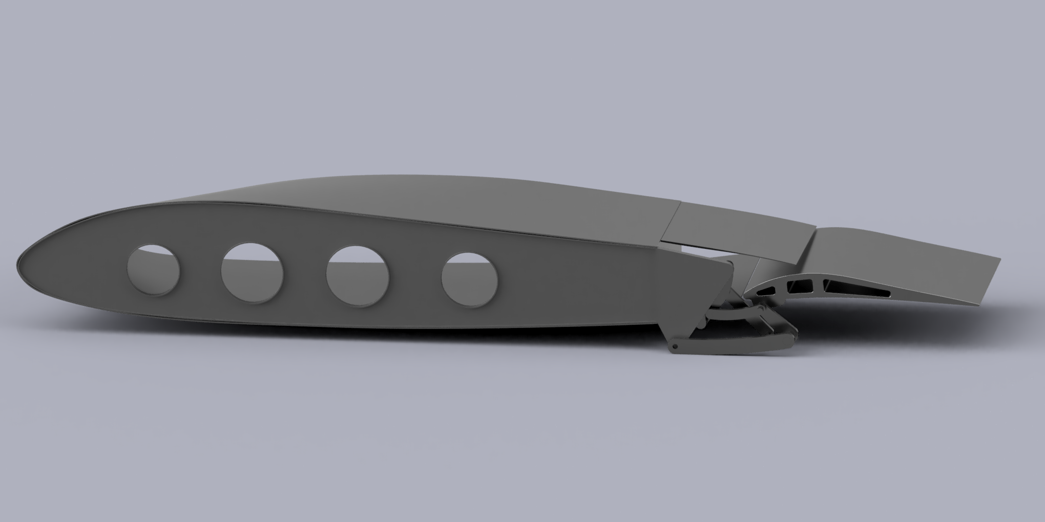
Image render
Desk Lamp
This time I wanted to create a model of a desk lamp. The design is based on a lamp from ikea but with a few modifications. The main change was replacing a longitudinal spring with a torsion spring which could be hidden inside the joint. I would have to do some more analysis to see if this is realistic. A potential problem that could arise is that by making the spring internal, it might take up too much space and the power cord would no longer fit inside the tubes. I also made a few cosmetic changes with the materials. I liked the way these materials contrast each other.
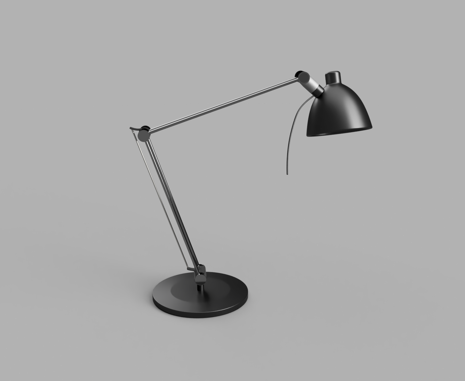
Final design
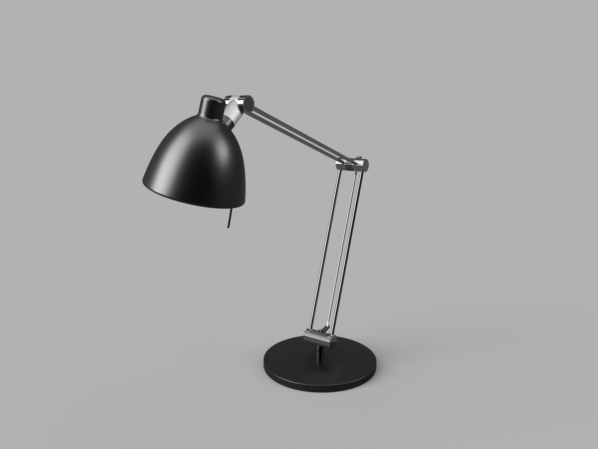
Final Design 2
Lamp animation
Blue Carpet Bench
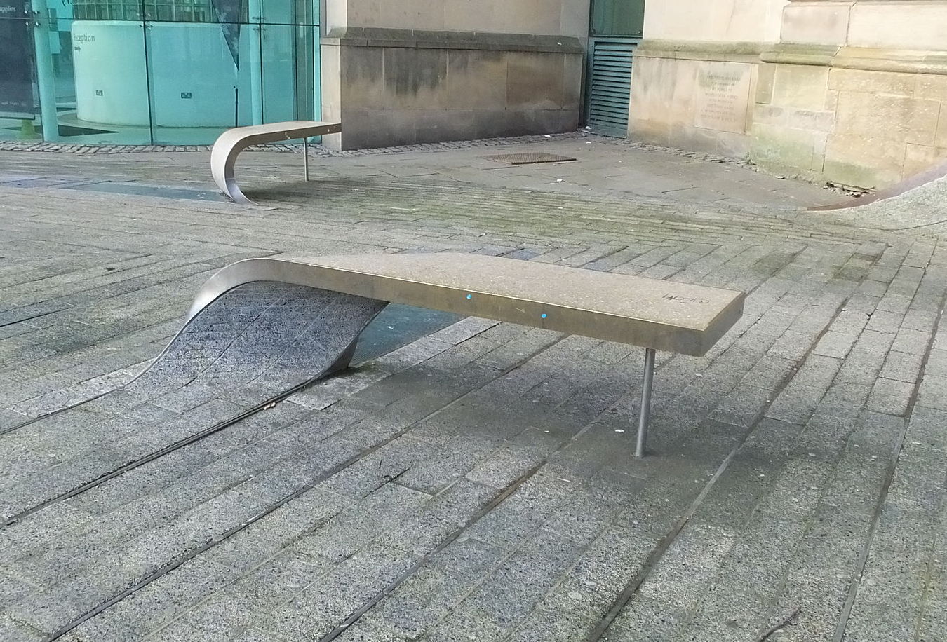
I have been strangely fascinated by Bezier and Hermite curves since first learning about them. Recently I found an art installation in Newcastle, UK which has a unique design for a bench. It is designed to look like a strip of carpet has been lifted and turned over to form a bench. My mind immediately wondered how you would fabricate such a bench and if you could define the curves. Turns out you can. Once I had a set of coordinates, I used the points to create a 3D model. I was also curious about loading, so I performed a quick deflection analysis.
procedure
This is the bench that I wanted to recreate.
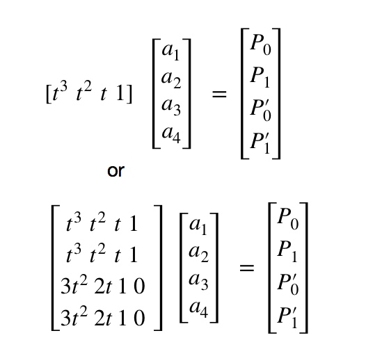
Finding the formula for the curve involves this matrix formula:
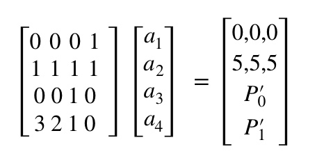
t = 0 at P0 and t =1 at P1. I arbitrarily set the start and endpoint to be (0,0,0) and (5,5,5) respectively. The matrix becomes:
Now we need to define the tangent vectors. We simplify things greatly if we orient the curve so that it starts along the x direction and ends along the y direction. the gradient has no z component since we assume the bench and ground are flat. orienting them along x and y means they only have one component. In this case I set the gradients to be (8,0,0) and (0,15,0), I played around with other numbers but these worked fine.
Now we can solve for the component functions [A] = [H]-1[P]
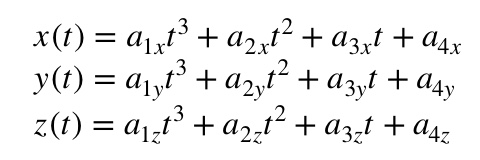
I the used matlab to plot the line. Below is the code:
	H = [0,0,0,1;1,1,1,1;0,0,1,0;3,2,1,0];
	P0 = [0,0,0];
	P1 = [5,5,5];
	Pp0=[8,0,0];
	Pp1=[0,15,0];
	P=[P0;P1;Pp0;Pp1];
	a=inv(H)*P;
	t = 0:.05:1;
	x = a(1,1)*t.^3+a(2,1)*t.^2+a(3,1)*t+a(4,1);
	y = a(1,2)*t.^3+a(2,2)*t.^2+a(3,2)*t+a(4,2);
	z = a(1,3)*t.^3+a(2,3)*t.^2+a(3,3)*t+a(4,3);
	plot3(x,y,z,’color’,'g')
Repeating this for the other three corners and you have a fully defined surface as shown below:
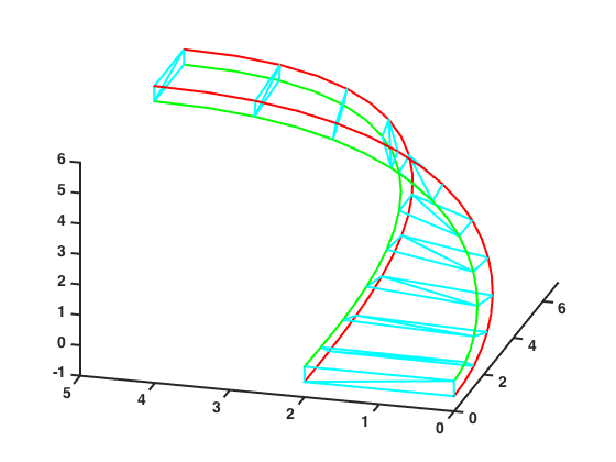
It is important to notice that the top of the ground becomes the bottom of the bench and vice versa. Now it was time to model the surface. I took a few of the control points I found using this method to create a rail that defines the path. I had the model fold in the other direction because in Matlab the coordinates are absolute, while in Fusion, they are relative and would have negative control points, and I don’t like negative numbers.
Below is my 3D model:
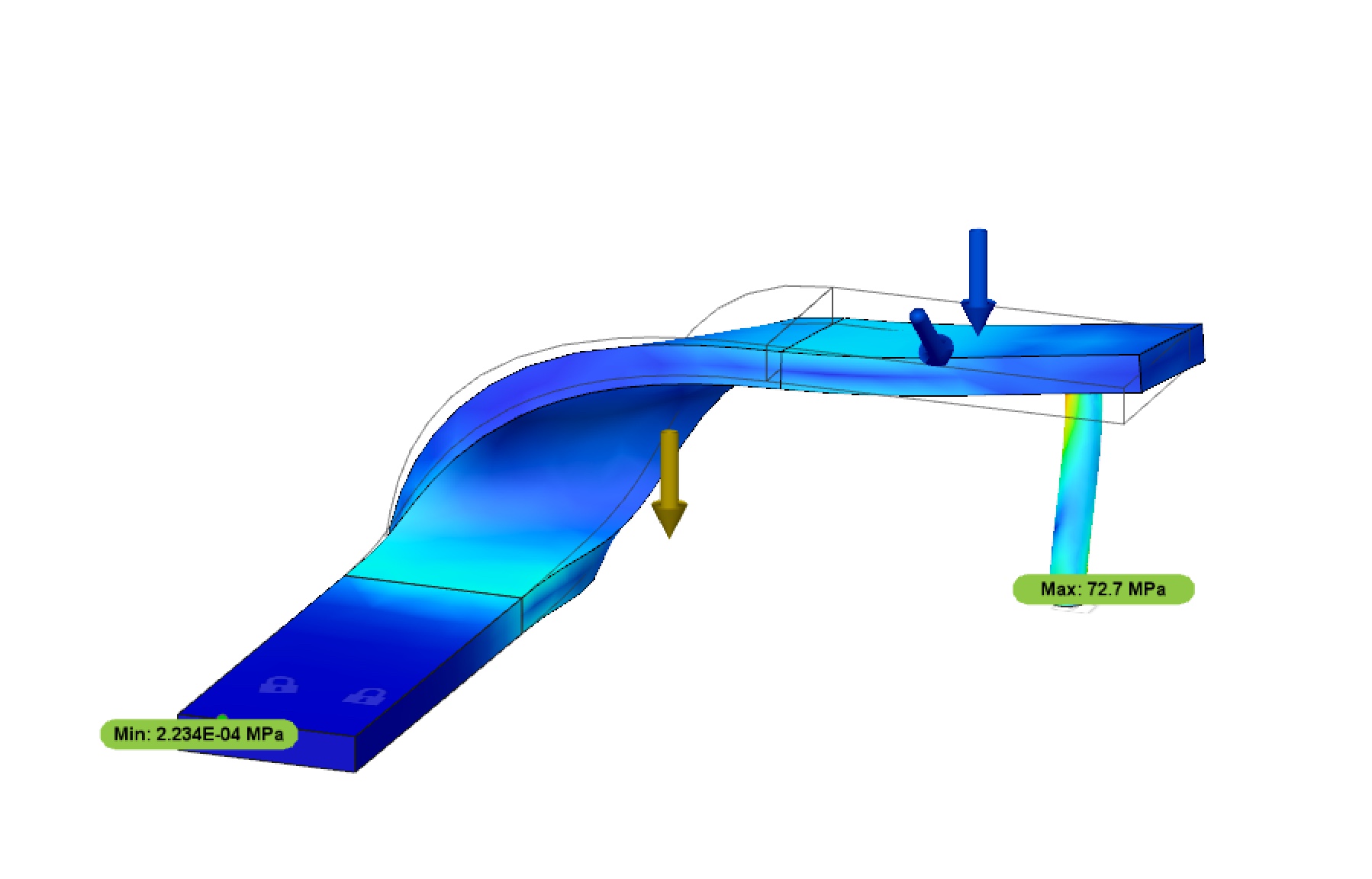
Loading Analysis
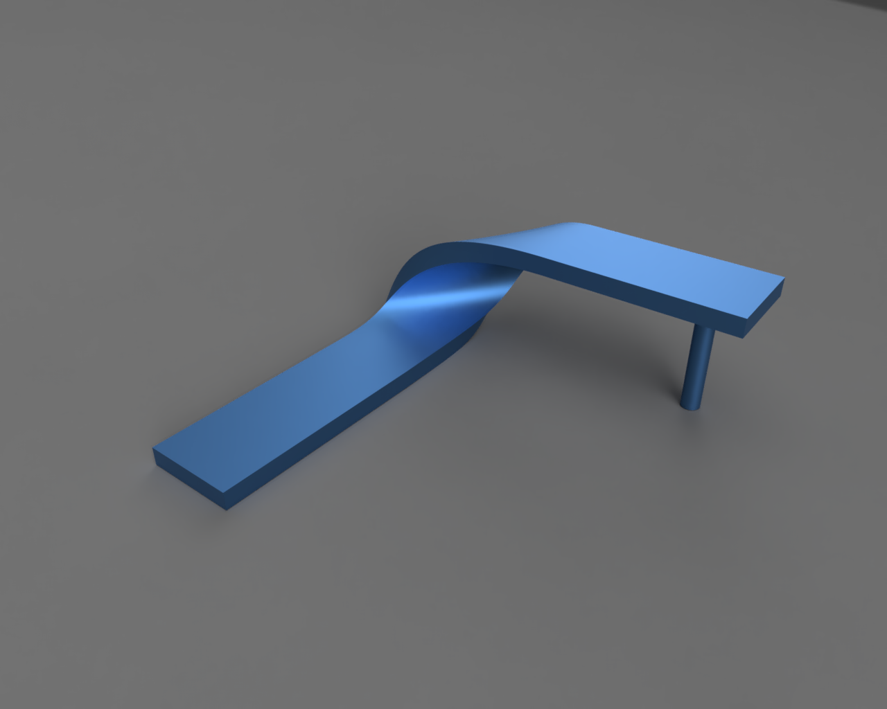
Front View
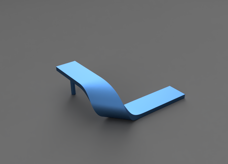
Back View