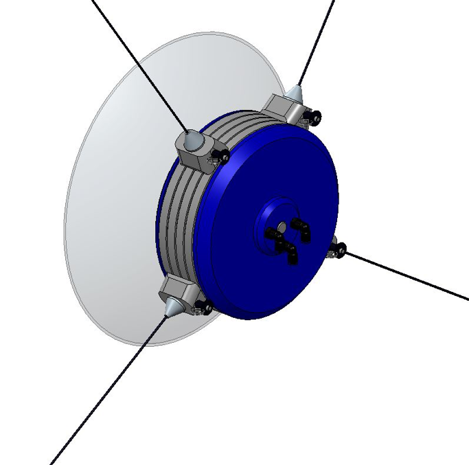
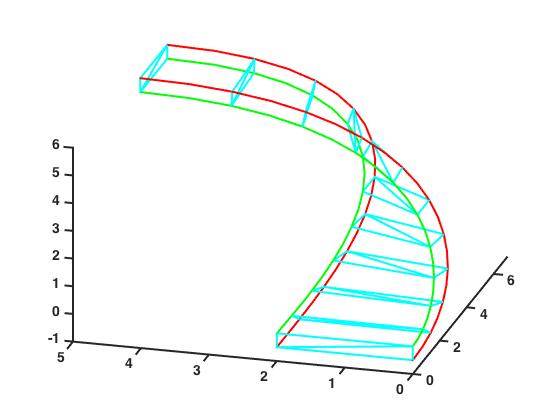
This project consisted of designing and controlling a robot capable of drawing on a variety of canvases of different sizes. The main goal was to design a robot that could assists artists in the creation of murals. During the initial research, we determined that the first stage of drawing a mural is drawing the initial outline, this process can be difficult and time consuming. The goal was not to eliminate artists completely, but instead to save time.
The robot is controlled by four stepper motors placed on the four corners of the mural. The main difficulty we encountered was determining how to control the robot. I was tasked with developing the algorithm that would generate the robot’s path.
View Project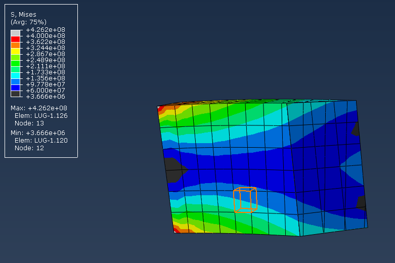
This project was for one of my FEA classes. For this project I studied the stresses typically encountered by a Baja vehicle during competition. Part one of the report studied the stresses under static loading.
See part 1 of report here
The second report analyzed the suspension under dynamic loading.
See part 2 of report here
View Project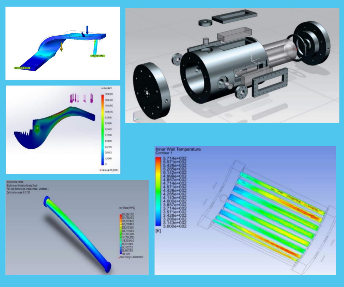
I have been fascinated with stress analysis and 3D modelling. 3D CAD provides a unique challenge, but once mastered, completing a new project becomes immensely rewarding. Included in this section are a series of projects I have worked on relating to Finite Element Analysis. Each project had unique challenges requiring knowledge of different fields within engineering.
Whenever possible we took a systems and model based approach for designing the products. The first step was to split the product into discrete sections with a series of requirements. After the requirements were listed, we set out to create a model of the project. Analyzing the different parts, ensuring the design was within the factor of safety. Finally, refinements were made to the model as necessary.
The goal of this is to showcase the variety of engineering software I have used and the wide variety of projects I have worked on. I learned a great deal working with a hands-on approach.

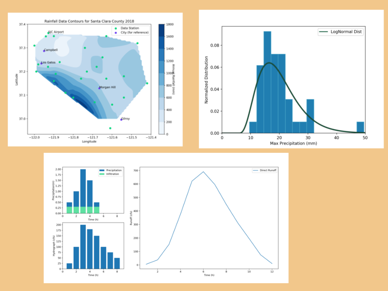
I have always been fascinated with hydrology, in fact, for one of my first science projects I created a small scale water treatment system. I wanted to demonstrate that even if water was brown and muddy, it is still mostly water and can be purified for future use.
Hydrology is fascinating because although it may seem simple and straightforward, it is really a fine balance of a wide variety of fields such as: Atmospheric Sciences, Fluid Mechanics, Infrastructure Engineering, Statistics, Probability, Geology, and most importantly, there is a lot of data involved.
Here I have combined several data visualization projects related to water. All of these projects were done using Python. Python is a great language, it is easy to learn and it has a great community. My only complaint is that parsing data is not as straightforward as it is using R or Matlab. However, it is a great overall language.
View Projects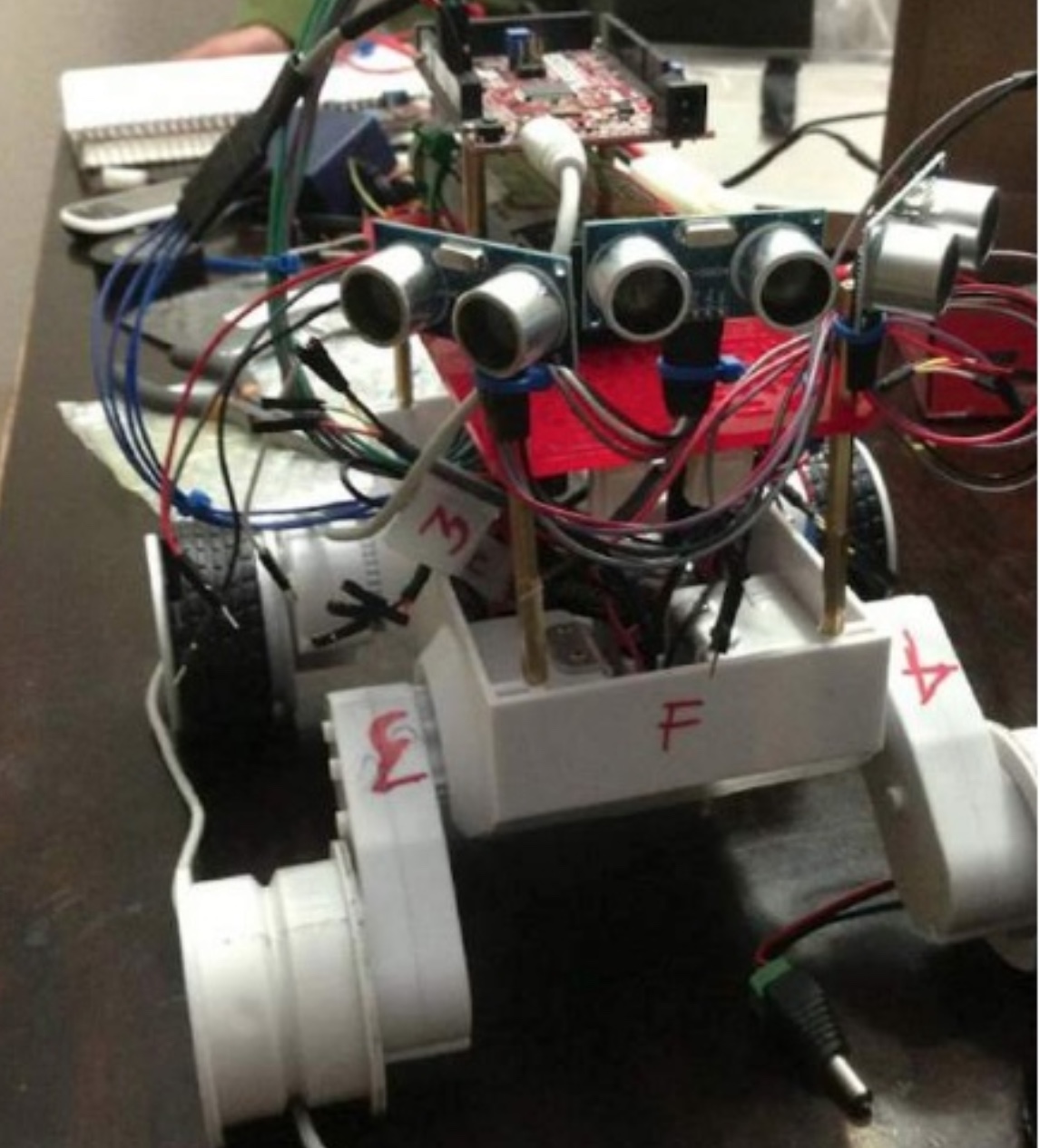
Autonomous robot for a Mechatronics class. The basic requirement for this project was to create a self driving robot capable of traversing a hallway and avoid any obstacles. Once this requirement was met, the secondary requirement would be to transmit information to any subsequent robots so that they may follow the same path.
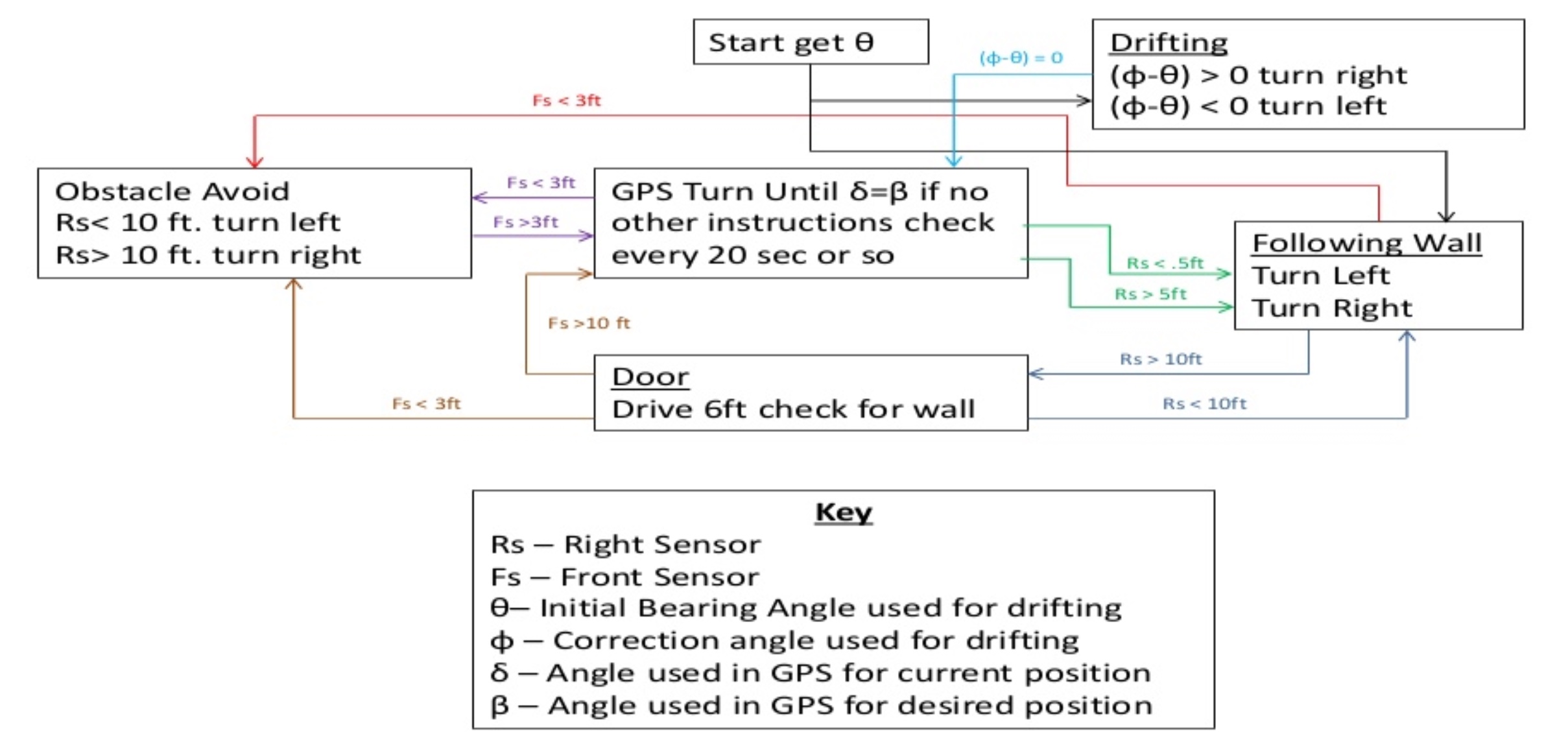
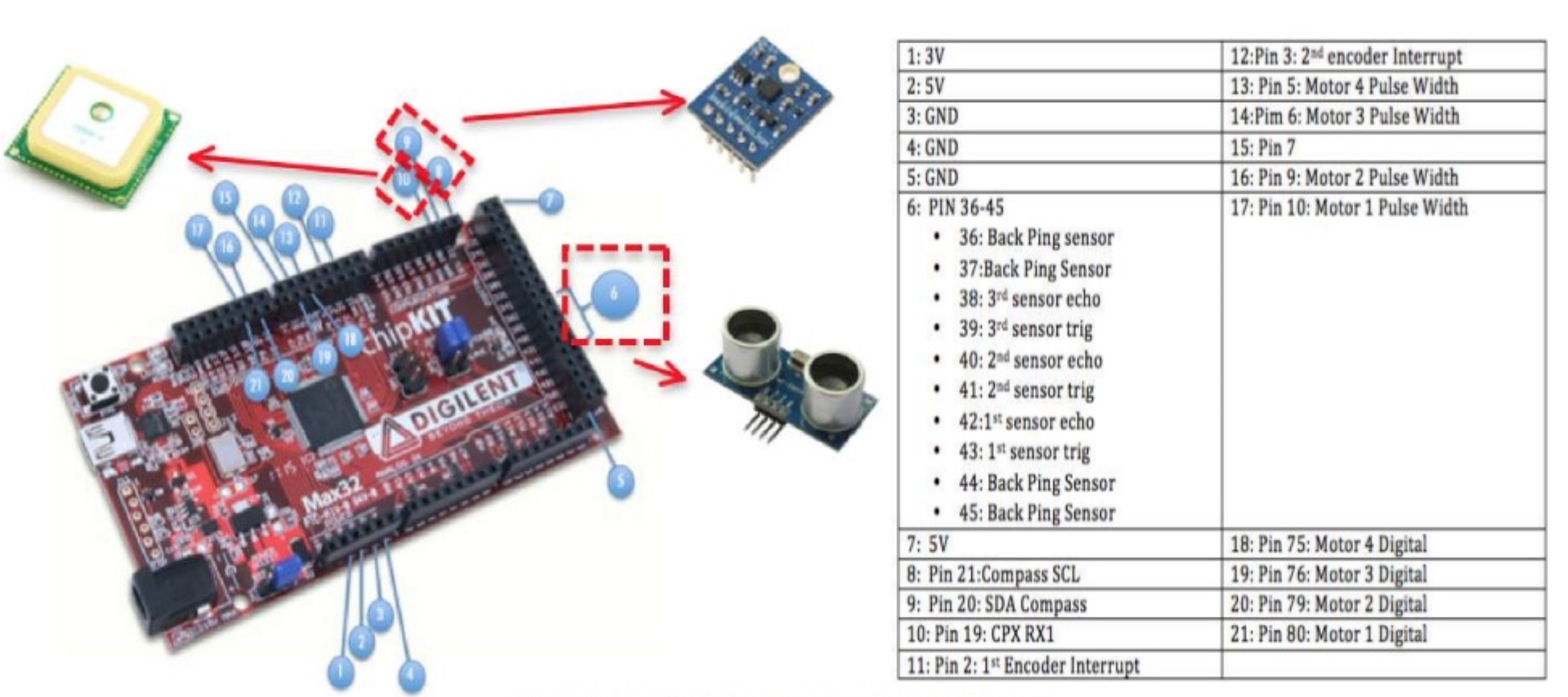
With this project, I came up with a novel idea about how to accomplish the second goal. I wanted to come up with a way to map the layout of the hallway as the robot traversed the hallway. I came up with a proof of concept that I discuss further here:
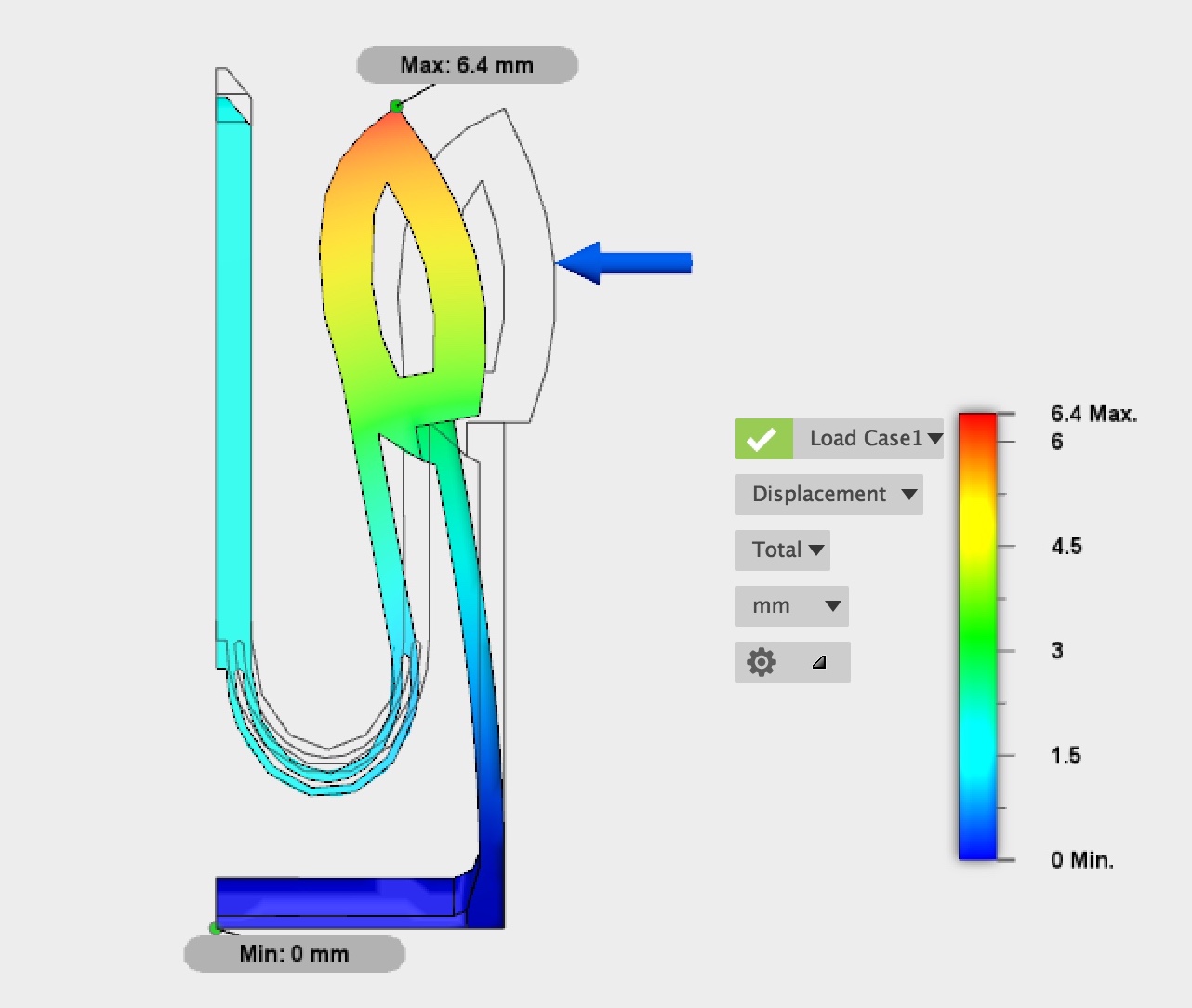
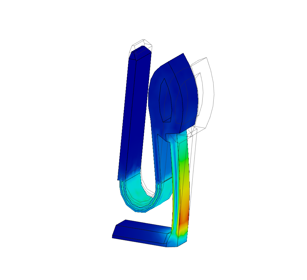
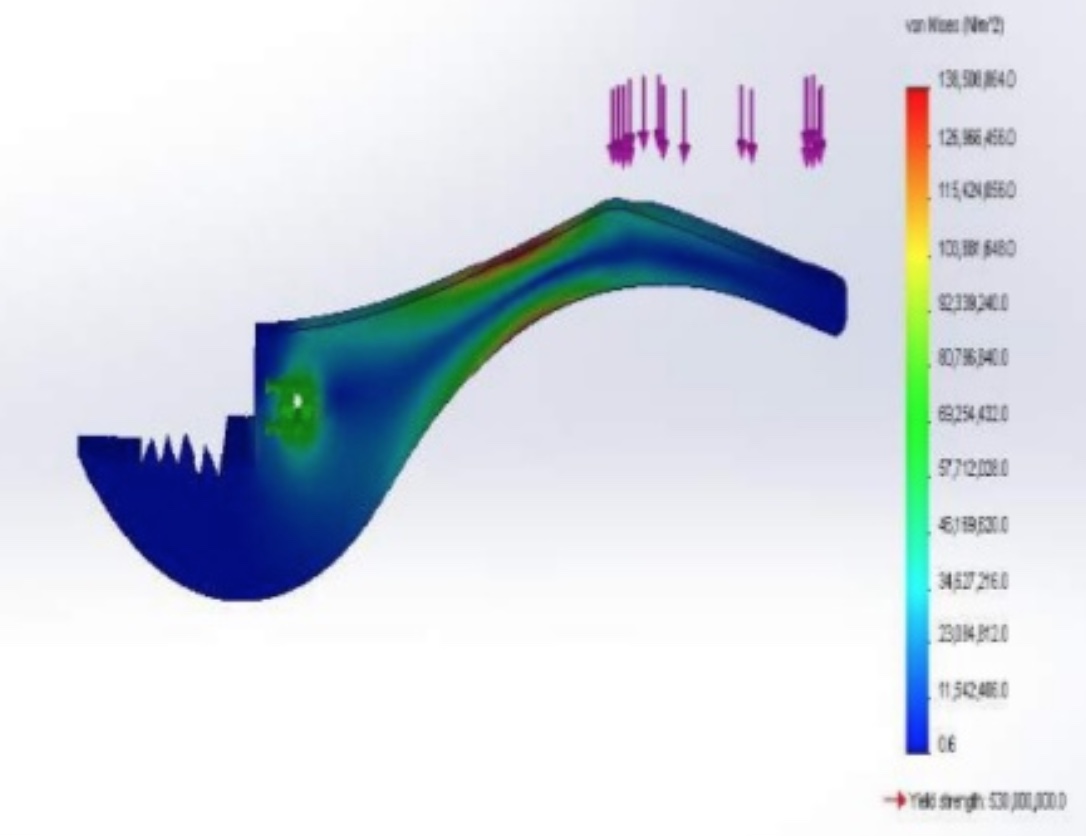
View ProjectThis buckle is one of my favorite projects I have ever worked on, it originally started as a way to replace a broken buckle on my backpack but I ended spending a lot more time than planned.
This buckle has undergone over 10 different iterations. The original design was a simple buckle, but after some quick FE analysis I discovered that the plastic was too brittle to withstand repeated deflections. I then borrowed some design ideas including the two ‘u’ connectors which act as springs. After running more FEA tests and refining the buckle by reducing stress concentrations, I reached a design I was happy with. I even included a whistle like the one in the broken buckle.
Finite element analysis here
First printing attempt failed. Currenty working on a redesign.